The Build Diaries - Imperial Dalek
Project: Imperial Dalek
Date commenced:
Screen appearance:
Date completed:
Build Notes:
Head dome
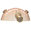
The head dome section is made up of several different parts, the head dome, the eye stalk and the dome lights. The dome is a fibre glass dome. You can make a dome but there is a reasonable amount of work, as you need to make a former and then with it, shape a huge blob of plaster. Then dry it off and coat it with release gel, then fibre glass it up to make a negative which will become the mould. Having made the negative mould, coat the inside with release agent and fibre glass your dome. When cured release it from the mould and finish it off. I knew from information read and conversations had, it was not always as easy as it sounds. I had no fibre glass skills and did not think it worth making one, when I could obtain a good one for £30.
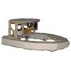
![]() After I'd read the guild plans (Dalek Builders Guild
has now closed, Project Dalek is a great alternative)
for the dome movement, I opted for a circle of wood
with four holes cut out and the eye stalk supports
mounted on it (as per diagram left). It is important
to test fit the and ensure it is positioned correctly
and is level. If not, your dome will never swing in a
level line! I attached the turning circle with 4 x
40mm fixing angles bent to match the dome angle. The
eye stalk assembly was attached to this assembly and
the eye stalk movement was added to the dome turning
circle prior to the head dome being attached.
After I'd read the guild plans (Dalek Builders Guild
has now closed, Project Dalek is a great alternative)
for the dome movement, I opted for a circle of wood
with four holes cut out and the eye stalk supports
mounted on it (as per diagram left). It is important
to test fit the and ensure it is positioned correctly
and is level. If not, your dome will never swing in a
level line! I attached the turning circle with 4 x
40mm fixing angles bent to match the dome angle. The
eye stalk assembly was attached to this assembly and
the eye stalk movement was added to the dome turning
circle prior to the head dome being attached.
Cutting the eye stalk slot in the Dalek dome was not easy and was quite nerve racking. You could only guess how much room the slot needed to be able to raise and lower the eye stalk. It was achieved by trimming a pilot hole and then enlarging it slowly to increase the size to try and achieve the desired The eye stalkeffect.
Much later in the build, almost at the end (after painting) the light bolt holes were drilled into the dome. The whole eye movement needed to be tested and checked. I then bolted them to the turning circle and glued them into the dome.
Lastly I drilled a hole in the centre of this to ensure that the locating bolt would make the dome turn from the centre each time.
The Eye stalk
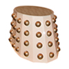
 The eye stalk circles are made from MDF padded with
two smaller thinner circles, one each side and filled
and smoothed to provide a chamfered outline. The four
discs are different sizes, measurements were obtained
from photos and other reliable sources of information.
The eye stalk circles are made from MDF padded with
two smaller thinner circles, one each side and filled
and smoothed to provide a chamfered outline. The four
discs are different sizes, measurements were obtained
from photos and other reliable sources of information.
The eyeball itself is made from the a modified stainless steel sugar bowl ! A disc of MDF was carefully cut to size and fitted to the end with another disc ontop, to create the different levels. Drilling the hole in the end to secure the bowl to the eye slak was really tricky as stainless steel is quite tricky to drill through. When assembled, filled and carefully sanded it was ready to bolt onto the eye stalk tube.
Dome Lights
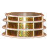
 The lights were made with two slices of tube, two
dished domes and two perspex or The ring and domed
dishacrylic rings cut to size with polished edges.To
built the dome lights, I began by carefully cutting
two 20mm slices of tube with a hand saw and then
lightly sanding any rough edges. Next I made two MDF
rings to go inside them so I could anchor the tube to
the dome. I then cut and polished two rings of 6mm
perspex. When complete they looked like large clear
polo mints. I then added the domed dishes bought from
EMA model supplies (see links page).
The lights were made with two slices of tube, two
dished domes and two perspex or The ring and domed
dishacrylic rings cut to size with polished edges.To
built the dome lights, I began by carefully cutting
two 20mm slices of tube with a hand saw and then
lightly sanding any rough edges. Next I made two MDF
rings to go inside them so I could anchor the tube to
the dome. I then cut and polished two rings of 6mm
perspex. When complete they looked like large clear
polo mints. I then added the domed dishes bought from
EMA model supplies (see links page).
Originally Minty had 12v 21w lights but I have changed to super bright white LED's as I melted my domes due to the heat output of the lamps in a confined space.
 The finished dome lightThis was one of the most
tricky parts of Minty to build and required precision
and lots of patience with the sanding and polishing of
the perspex rings. The last photo shown in this
section is of a completed dome light. You can see the
bolts that will be used to fix the light assembly to
the head dome.
The finished dome lightThis was one of the most
tricky parts of Minty to build and required precision
and lots of patience with the sanding and polishing of
the perspex rings. The last photo shown in this
section is of a completed dome light. You can see the
bolts that will be used to fix the light assembly to
the head dome.
The wiring for the lights is first attached to the head ome and the bulbs are then pushed through thte opeing in the bottom of the dome light as it is lowered into position and bolted on. Take care to ensure that is you use LED's that the correct voltage is used in the dome light circuit or you could blow up your LED's.
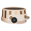
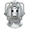
Head
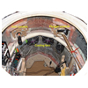
I was very lucky to be able to purchase a Cyberhead. The Cyber head was good but I added some detail to it, where it needed extra detail to make it into Attack of the Cybermen style. The same was true of the shoulders or chest section.
After inspecting the head and comparing it to many
different photos, I began to modify it to add
finishing touches. Firstly I cut holes in the sides of
the head and added the fine mesh behind the handles or
Cyber ears. Inside the cyber head I also added some
detail to the outside of the head ontop at the front
and gave it a respray as it had been knocked about a
bit.
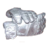
After wearing it for the first time in warmer weather, I knew it needed to have a little air circulation system. The head was modified to take three small 40mm 12v fans. This provided some much needed air circulation! A 9v battery will run each fans, which provides necessary airflow inside the head, if it is worn for long periods ! In the photo you can see two of the three fans. One is situated on the chin and the other two are on the sides. All the wiring is sealed in so that there is no possibility of short circuit or any minor shock due to dribble contacting the wiring. The wires connect to the chest unit, behind which is a switch, so I can operate the fans without having to remove the head each time.
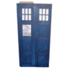
The roof
It seemed logical to build the roof and light together as they needed to be part of the same section of the TARDIS build. Click here to skip down to the information about the TARDIS light.
The logical next step was the roof. This was the only part that I had a problem with. I incorrectly recorded one of my measurements and so calculated the wrong length of wood to cut. This was not too disastrous as I over allowed as opposed to under calculated my length.
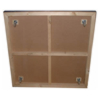
 The roof was fun but tricky to make. I needed to
make a two square frames and then sit one on top of
the other. That would make the box on a box shape that
is so much a part of the TARDIS roof. I then had to
allow a slight slope up to the roof light platform. I
wanted it to be one piece but to be as light as
possible since I was going to have to lift it into
position, possibly on my own.
The roof was fun but tricky to make. I needed to
make a two square frames and then sit one on top of
the other. That would make the box on a box shape that
is so much a part of the TARDIS roof. I then had to
allow a slight slope up to the roof light platform. I
wanted it to be one piece but to be as light as
possible since I was going to have to lift it into
position, possibly on my own.
The build went really well, it was great fun assembling it all, like a giant model kit but having to machine all the parts in order to advance the build. I would say it was the most satisfying part to build since it was most tricky out of all the parts I had built up to that point. I then needed to sit the roof on something, in order to be able to locate it on top of the TARDIS.I designed a collar to fit on the top of the side panels that the roof could sit inside of. It also needed to blend into the TARDIS so you did not know how it was assembled from the outside. I removed the end caps from the top of the posts and used the mountings that they located onto as my fixing points. I decided to use the top part of the posts as markers to locate the roof inside and also stop it slipping out of position. This seemed to work well, however after two or three times of needing to disassemble the roof sections in the course of production it became obvious this was not a cunning plan and I screwed then both together. This was an excellent move as it greatly strengthened both parts and produced a roof section that was very strong and stable when being lifted into position.
Head
dvfkjv dflvk dflvkm ldfvm dfmvlfd mkvlkmdf v